A complete guide on how to design for permanent mold casting.
Every engineer has done it at one point in their career. They discovered a need for a new product. Designed the perfect part. Even 3D printed a prototype.
But when they begin researching metal casting processes, they make an unfortunate discovery. Their design is 3D printable, but not castable.
It’s important to consider the manufacturing process early in designing. Each casting method has its own unique design standards. By following these design guidelines, you can rest assured that your part will be easily manufactured!
Here are 7 important specs when it comes to designing for aluminum permanent mold castings.

Wall thickness is the most crucial design standard. Since the permanent mold process is gravity-fed and castings solidify quickly, a minimum wall thickness allows adequate metal flow.
To make your design permanent-mold friendly, we recommend a wall thickness of at least 0.180 inches.
Try to avoid isolated thin or thick sections. These can impact the flow and solidification of metal, cause shrinkage, and lead to other defects.
If your design’s wall thickness is non-negotiable and on the borderline of permanent mold requirements, molds can be equipped with vents and chills to help alleviate issues during casting. However, inadequate wall thickness increases your potential for higher scrap rates.
Another alternative is to cast your part with thicker walls, then use secondaries, like machining and polishing, to shave off excess metal.
Yet overall, if you wish to permanent mold cast your product, it is best to design the part with adequate wall thickness from the start. This minimizes opportunities for error. Otherwise, consider choosing a manufacturing method that specializes in isolated thin or thick walls.
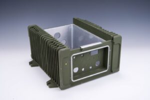
Slightly rounded corners make your part stronger! We recommend at least 0.030 inches.
Sharp corners cause…
We suggest casting your part with the recommended fillets and radii, then machining and polishing your desired corners. This is a common operation in the permanent mold industry.
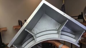
When the as-cast part doesn’t exactly meet your desired tolerances, you may choose to add on secondary operations, such as machining or polishing.
When machining is required, your design must account for extra material. If you do not include a machine stock allowance, your part’s final dimensions may be out of spec.
Machine stock allowances for permanent mold casting start at 0.045 for 0 to 6 inches, then increases as dimensions increase. See the chart below.
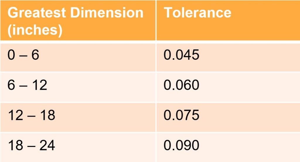
*per surface, not per dimension
Draft is very important in permanent mold casting. Draft…
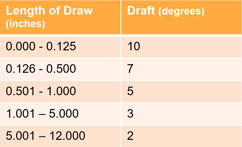
In the permanent mold process, there is no such thing as too much draft! In general, we recommend 3 degrees of draft, but minimum draft requirements are dependent on depth. See the chart below.
Cored holes can save time in machining operations.
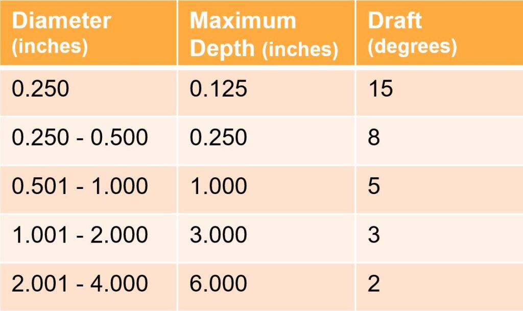
Similarly, minimum cored hole draft requirements are dependent on depth and diameter.
The parting line is where the mold top (cope) and bottom (drag) separate.
Understanding the parting line is important when designing draft and understanding concentricity tolerances.
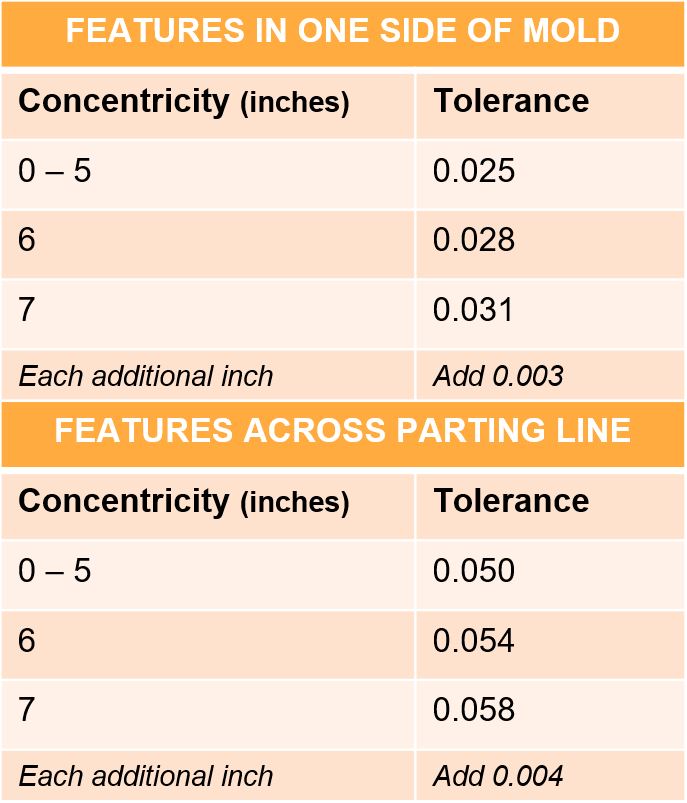
The parting line affects your concentricity tolerances. For example, for features across the parting line, you need more room in your tolerance than features limited to one side of the mold.
For features on one side of the mold, expect a tolerance of 0.025 for up to 5 inches. Add 0.003 for each additional inch. See chart below.
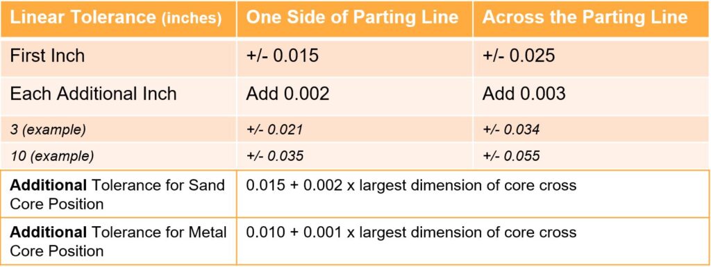
If you design within linear tolerances, your part will meet specs as-cast. However, if you design outside of these linear tolerances, your part may require secondary machining.
The permanent mold linear tolerance is +/- 0.015 for the first inch for features on the same side of the parting line. Add 0.002 for each additional inch.
For features across the parting line, the linear tolerance is +/- 0.025 for the first inch. Add 0.003 for each additional inch. Tolerances can vary even more when there is a sand core or metal core.
Here’s one major benefit of the permanent mold process: Permanent mold has very tight flatness tolerances compared to many other casting processes, such as sand casting.
The permanent mold flatness tolerance is 0.020 for the first 6 inches. Add 0.002 for each additional inch.

While designing, consider the extra capabilities of the permanent mold process. Two unique design opportunities include cast inserts and sand cores.
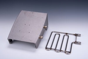
You can cast your product around metal inserts, directly embedding them into your part. These metal inserts are tightly held in place, becoming extremely functional.
For example, you can directly insert bearings, tubing, heating/cooling channels, and more into your product during the casting process.
Sand cores are used to create hollow cavities in the casting. Sand cores can be used to create a complex geometry inside of your part. The cavity might be used in assembly, or to channel wire through the product.
The core is laid in the mold and cast inside the part. Then, the sand is baked or shaken out. We call this process semi-permanent mold.
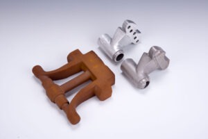
Read more about this multi-cavity semi permanent mold casting!
Email Batesville Products today! Our engineering & sales teams will review your design and provide a quote!