


A complete guide for design engineers to help you design for manufacturing!
By following this design guide, your part will be more cost & time efficient to manufacture by reducing scrap or defect potential. By knowing all the manufacturability requirements upfront, you’ll speed up the design process, meaning a quicker time to market.
If you optimize your design, you unlock all the great benefits of aluminum permanent mold casting:
Here’s our 2024 design guide with 16 key design standards.
Note: all guidelines are for aluminum permanent mold casting only. Foundries outside of Batesville Products may have slightly different standards.
We recommend a wall thickness of at least 0.180 inches. Since permanent mold castings are gravity-fed and aluminum solidifies quickly, this ensure proper metal flow and solidification during casting.
Avoid isolated thin or thick sections. These can negatively impact flow and solidification, causing shrinkage and other defects.
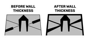
Need thinner walls or dramatic changes? Secondaries like machining and polishing can shave down excess material.
We recommend fillets & radii at least 0.030 inches. These make your part stronger!
Sharp corners cause high stress, cracking, and tearing.
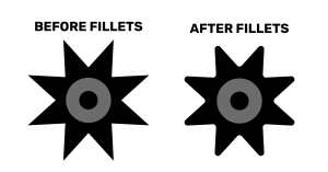
If your casting needs a 90-degree corner for assembly, consider secondary machining. This is common practice in casting.
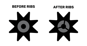
Ribs make your casting stronger without adding excess thickness, weight, or material cost to your design.
Ribs and gussets also help metal flow into hard-to-fill features (like bosses).
In you’re designing ribs, remember:
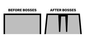
Bosses aren’t always needed, but sometimes designers add them to position parts for assembly or fixate two pieces together.
If you’re designing bosses, remember:
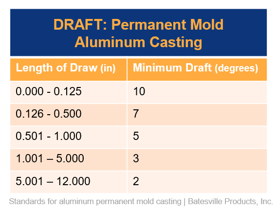
There’s no such thing as too much draft in casting! Draft…
Because draft is all about helping smoothly remove the part from the mold, draft should always move away from the parting line.
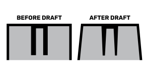
Minimum draft requirements depend on depth. Shorter walls require more draft than tall walls. For example, a 0.5 inch wall requires about 7 degree draft, while a 5 inch wall requires about 3 degree draft.
Also, outside walls require slightly more draft than internal walls.
Note: Due to the nature of steel permanent molds, permanent mold castings generally require more draft than sand castings.
Holes and pockets can be designed into permanent mold castings. These are created by steel cores that are pulled in and out of the mold during casting. The steel cores are often part of your permanent mold, powered by hydraulics.
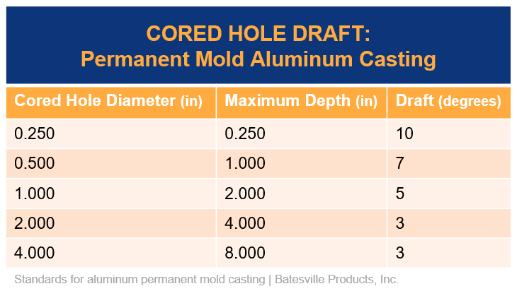
Your hole design should include draft to ensure the steel cores can easily slide in and out of the casting.
Cored hole draft requirements depend on diameter and depth.
After casting, cored holes can be fully machined to remove draft. Cored holes make machining quicker and easier!
Alternatively, if your holes cannot have any draft, use sand cores to create holes and pockets.
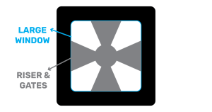
Holes and windows can make manufacturing challenging because they often block metal flow.
For small holes and windows, add bridges that can be trimmed out later during machining. These bridges will help metal flow throughout the entire part.
For large windows, add gates and risers that can be cut out later. Gates and risers are part of your tooling design. Metal is poured directly into the gates and risers, which then fill the rest of the mold cavity.
Holes and windows should always have more draft than any other feature. Draft prevents tearing, binding, or twisting during ejection.
Ejectors pins, or knock out pins, are part of your permanent mold tooling. The pins help nudge the casting out of the mold. Each pin will leave a tiny ring mark on the surface of the casting that can be removed with machining or polishing.
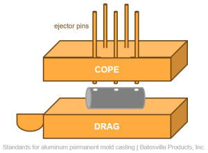
The number of pins, location, and size depends on the size and complexity of the casting.
It’s important to expect ejector pin marks on your permanent mold casting so you can set accurate surface expectations and tolerances. If you need a class A surface finish, note on your print that ejector pin marks should be polished out.
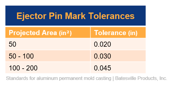
Ejector pin mark tolerances start at 0.020 inches for a projected area up to 50 inches squared.
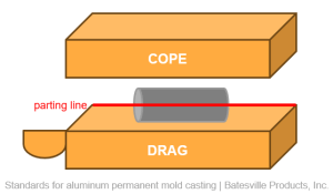
The parting line is the seam where the cope (top of the mold) and drag (bottom of the mold) separate. The parting line can often be seen unless you remove it with a quick and easy machining or polishing operation.
Improperly placed parting lines can increase flash and impact metal flow and tolerances.
Often, your foundry will handle tooling design. They will place the parting line in the best location to produce the best part possible. So, it’s not something you need to worry about. But, you need to be aware of its location and how it impacts your surface finish and tolerances. Communicate your expectations with the supplier.
Features on the same side of the parting line can hold tighter tolerances than features split across the parting line. (See linear tolerances and concentricity tolerances).
To hold very tight tolerances, we recommend designing complex and critical components to be on the same side of the parting line.
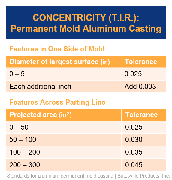
The permanent mold concentricity tolerance for features on the same side of the mold starts at 0.025 inches for a diameter up to 5 inches. For each additional inch, add 0.003 to the tolerance. For example, the concentricity tolerance for a 6 inch diameter surface is 0.028 inches.
Permanent mold has very tight concentricity tolerances in comparison to sand casting. Aluminum sand casting concentricity tolerances for features on the same side of the mold start at 0.050 inches (double that of permanent mold!).
Features across the parting line have a slightly looser concentricity tolerance.
For features across the parting line, permanent mold concentricity tolerances start at 0.025 for projected areas between 0 and 50 inches squared. For areas 50 to 100 inches squared, the tolerance increases to 0.030.
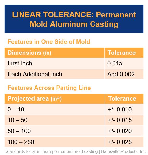
The permanent mold as-cast linear tolerances depend on parting line location. Again, for tighter tolerances, design critical features on the same side of the mold rather than across the parting line.
If your design requires tolerances outside of these as-cast linear tolerances, you’ll need to add a secondary machining operation.
Permanent mold linear tolerances for features in one side of the mold are +/- 0.015 for the first inch. Add 0.002 for each additional inch.
Permanent mold has very tight linear tolerances in comparison to sand casting. Aluminum sand casting linear tolerances for features on the same side of the parting line start at 0.030 inches (double that of permanent mold!).
Permanent mold linear tolerances for features across the parting line are +/- 0.010 for projected areas between 0 and 10 inches squared. For areas 10 to 50 inches squared, the tolerance is 0.015. For 50 to 100 inches squared, 0.020. And for 100 to 250 inches squared, 0.025.
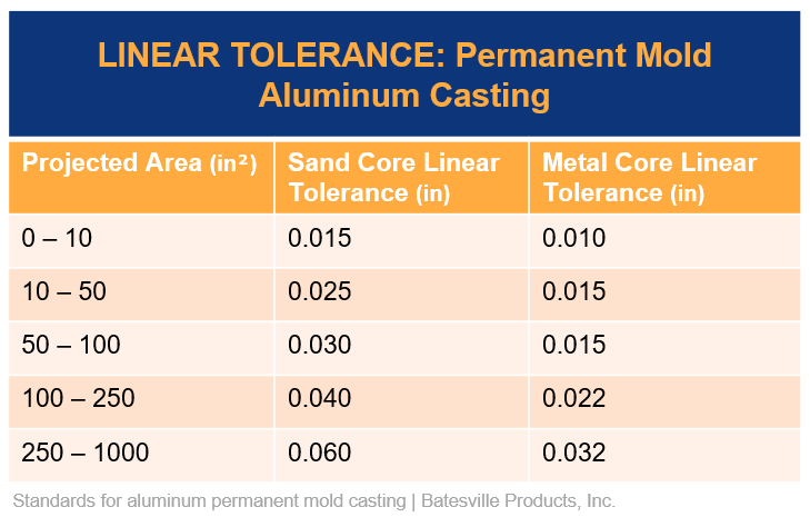
As-cast linear tolerances can vary when there is a sand core or metal core involved in the casting process.
Again, secondary machining can help achieve tighter tolerances.
Sand cores are non-reusable inserts used to create hollow channels or passageways in the casting. This process is called semi-permanent mold.
Linear tolerance for sand cores starts at 0.015 for projected areas between 0 and 10 inches squared. For areas 10 to 50 inches squared, the tolerance is 0.025. For 50 to 100 inches squared, 0.0030. For 100 to 250 inches squared, 0.040. And for 250 to 1,000 inches squared, 0.060.
Unlike sand cores, metal cores are reusable, made of steel, and built into your mold. They slide in and out of the casting.
Linear tolerance for metal cores starts at 0.010 for projected areas between 0 and 10 inches squared. For areas 10 to 100 inches squared, the tolerance is 0.015. For 100 to 250 inches squared, 0.022. And for 250 to 1,000 inches squared, 0.032.
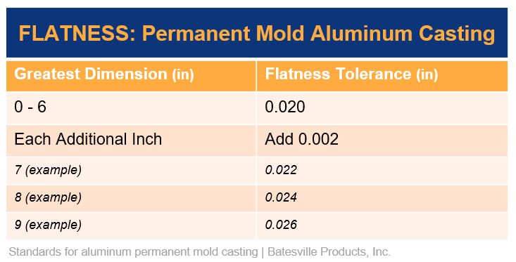
The permanent mold flatness tolerance is 0.020 for the first 6 inches. Add 0.002 for each additional inch.
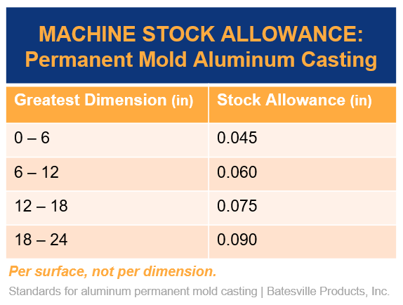
For even tighter tolerances, you can add secondary machining. If machining, add extra stock material. Machine stock allowance ensures your final part dimensions are in spec.
Machine stock allowances for permanent mold casting start at 0.045 for 0 to 6 inches, then increases as dimensions increase.
Note: allowances are per surface, not per dimension.
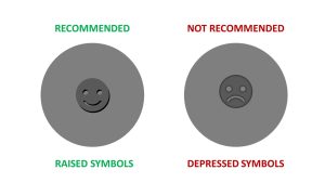
Permanently brand your product during the casting process with logos, symbols, and letters!
Use raised symbols on a flat surface. We do not recommend depressed symbols. Depressed symbols increase tooling cost and are more subject to mold wear and damage.
If you prefer depressed symbols, we recommend instead creating a depressed section, then placing a raised symbol inside.
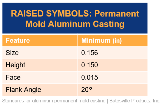
For your label to accurately appear, follow these size minimums.
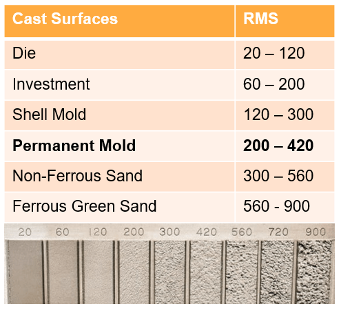
The average as-cast permanent mold surface finish is 200 to 420 RMS. This is smoother than sand casting (typically 300 to 560 RMS), but rougher than die casting (typically 20 to 120 RMS).
However, it’s important to note that permanent mold castings typically have lower-porosity than sand or die castings. This means you can add machining and polishing operations without the risk of opening up porosity and inclusion defects.
For an even smoother surface, consider secondary machining or polishing. Readily available aluminum casting finishes include:
Again, all standards presented are for permanent mold aluminum casting only. All tolerances are as-cast (not accounting for the secondary machining or polishing).
Permanent mold casting has so much opportunity for complex designs. By following this 2024 design guide, you’ll maximize all the great benefits of permanent mold casting AND save time and money manufacturing your design!
As always, if you have questions or want us to take a look at your design, don’t hesitate to reach out!
Subscribe to learn more about permanent mold casting, such as our industry webinars and other content that will help you navigate the world of metalcasting.
"*" indicates required fields

 Guides