There are 3 main things to keep in mind when designing for permanent mold: wall thickness, radius, and draft. In this engineering guide, we will walkthrough what those requirements are and other permanent mold design standards.
And remember: If you have any questions, our in-house engineering and sales teams are eager to help!


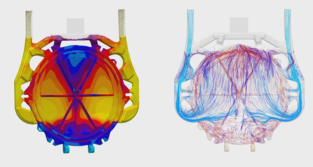
Having too thin of walls will impact the flow and solidification of metal. At BPI, we recommend designing your part with at least an 0.180 inch wall thickness.
It is also important to keep in mind that isolated thick or thin sections may result shrinkage or other defects. While we can add cooling and venting to help this issue, it is often better to design your part to minimize potential issues before they have the chance to occur.
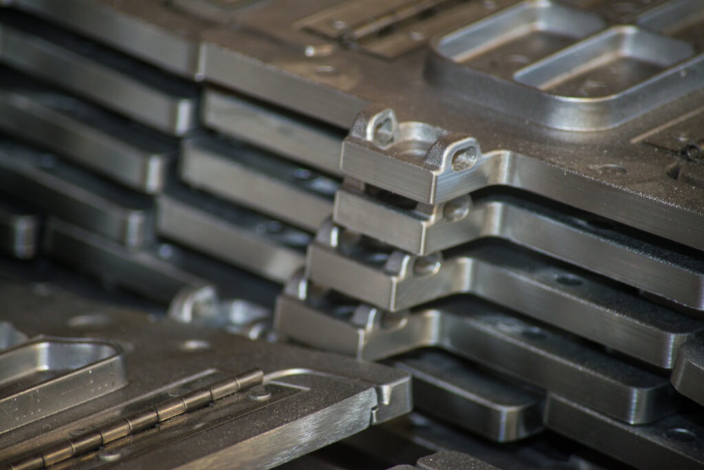
Sharp corners designed into permanent mold castings often lead to stress, cracking, or tearing defects. Therefore, we recommend designing corners slightly rounded with a 0.030 inch radius.

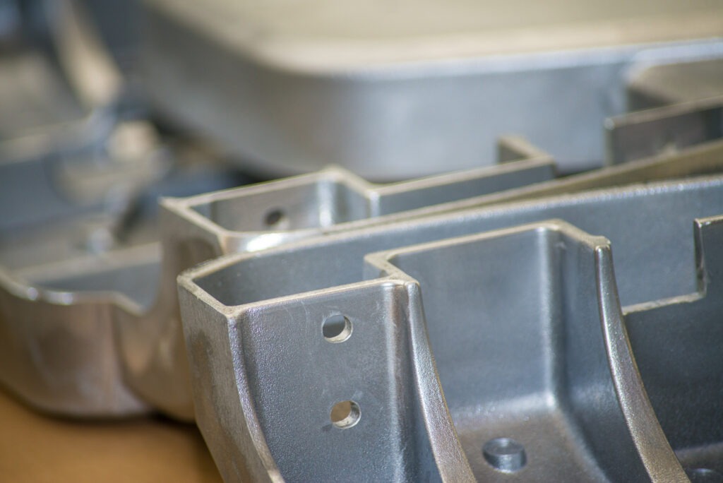
Draft helps with the ejection of your part from the mold, extending mold life and resulting in cleaner castings. The industry standards for permanent mold draft design are…
If your part requires a cored hole, you must also take into account its depth and draft. The industry standards for cored hole depth and draft are…

When basic linear tolerance on one side of the parting line ranges from 0 to 1 inch, the base tolerance is +/-0.015, with each additional inch being +/-0.002.
Additional linear tolerance across the parting line is added as a function of the projected parting face surface area.
As for flatness, if your greatest dimension ranges from 0 to 6 inches, your base tolerance is typically +/-0.020, with each additional inch being +/-0.002
Concentricity on the same plane ranging from 0 to 5 inches has a typical base tolerance of +/-0.025, with each additional inch being +/-0.003
On the contrary, concentricity across the parting line ranging from 0 to 10 inches has a typical base tolerance of +/-0.040, with each additional inch being +/-0.003
If your greatest dimension is from 0 to 12 inches, the machine stock allowance should be 1/16
If your greatest dimension is from 12 to 18 inches, the machine stock allowance should be 3/32
If your greatest dimension is from 18 to 24 inches, the machine stock allowance should be 1/8
Our engineering and sales teams are available to answer any questions you have! We love talking shop. Give us a call at (812) 537-2275 or email us at sales@batesvilleproducts.com
If you’re considering a permanent mold casting project, we can offer valuable insight that could save your company time, money and resources.